During the autumn of 2021, I was enrolled in ME 102: Foundations of Product Realization as part of the core curriculum for my Product Design major at Stanford University. One of the assignments was to use Computer-Aided Design to design, laser-cut, and assemble a non-rectangular box (meaning two or more sides needed to join together at a non-right angle) without the use of any adhesives. The only approved methods of conjoining the box sides were using interlocking tabs and fasteners, and both needed to be implemented somewhere in the box design.
Concept Sketches
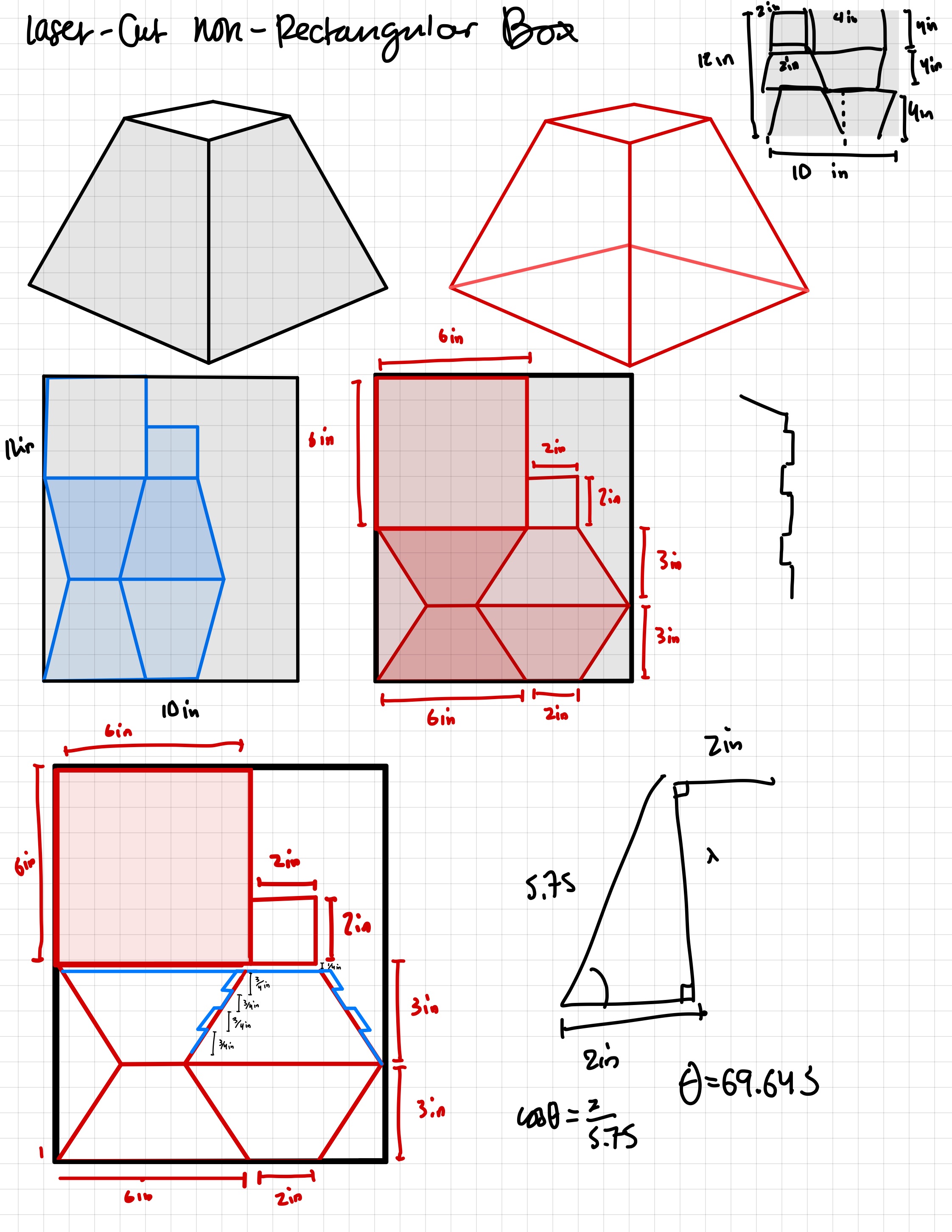
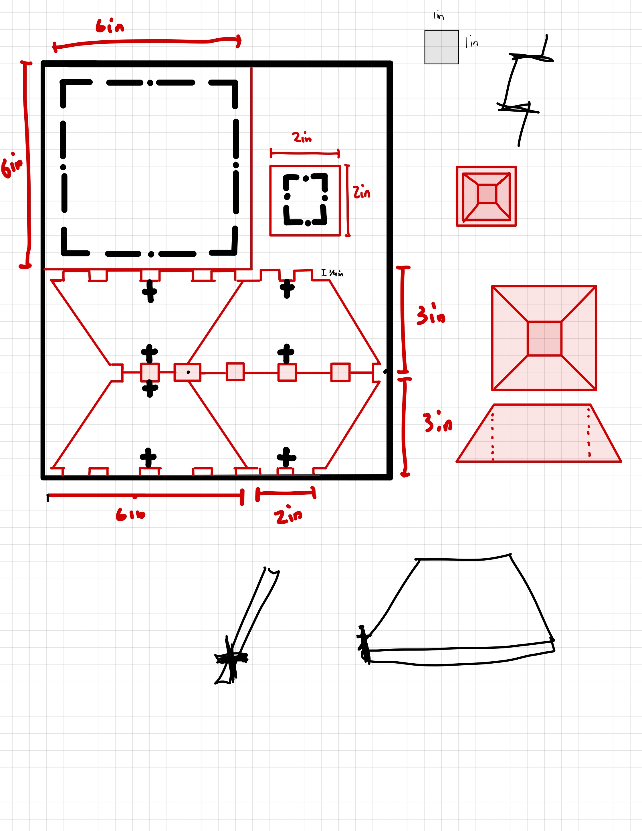
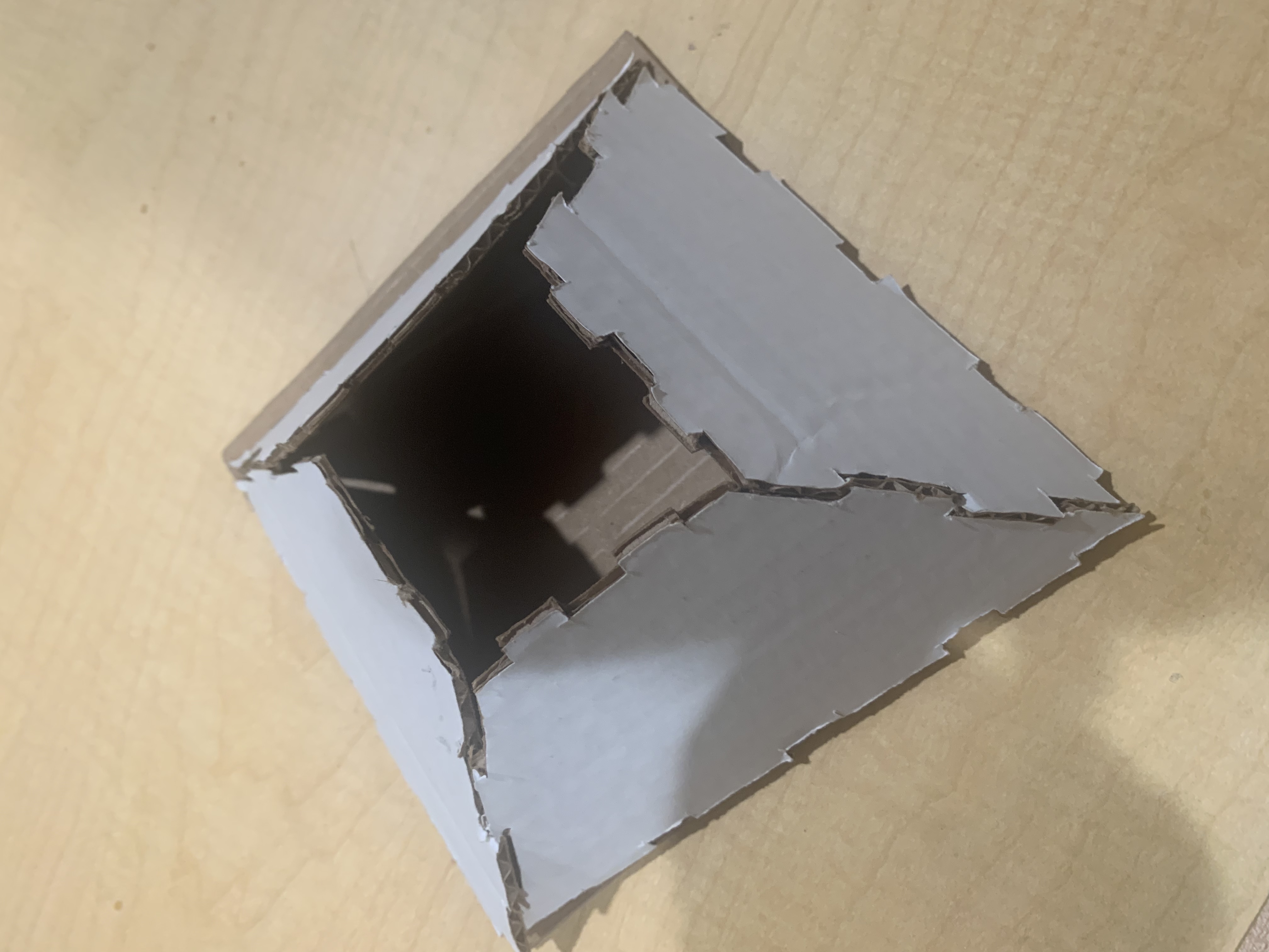
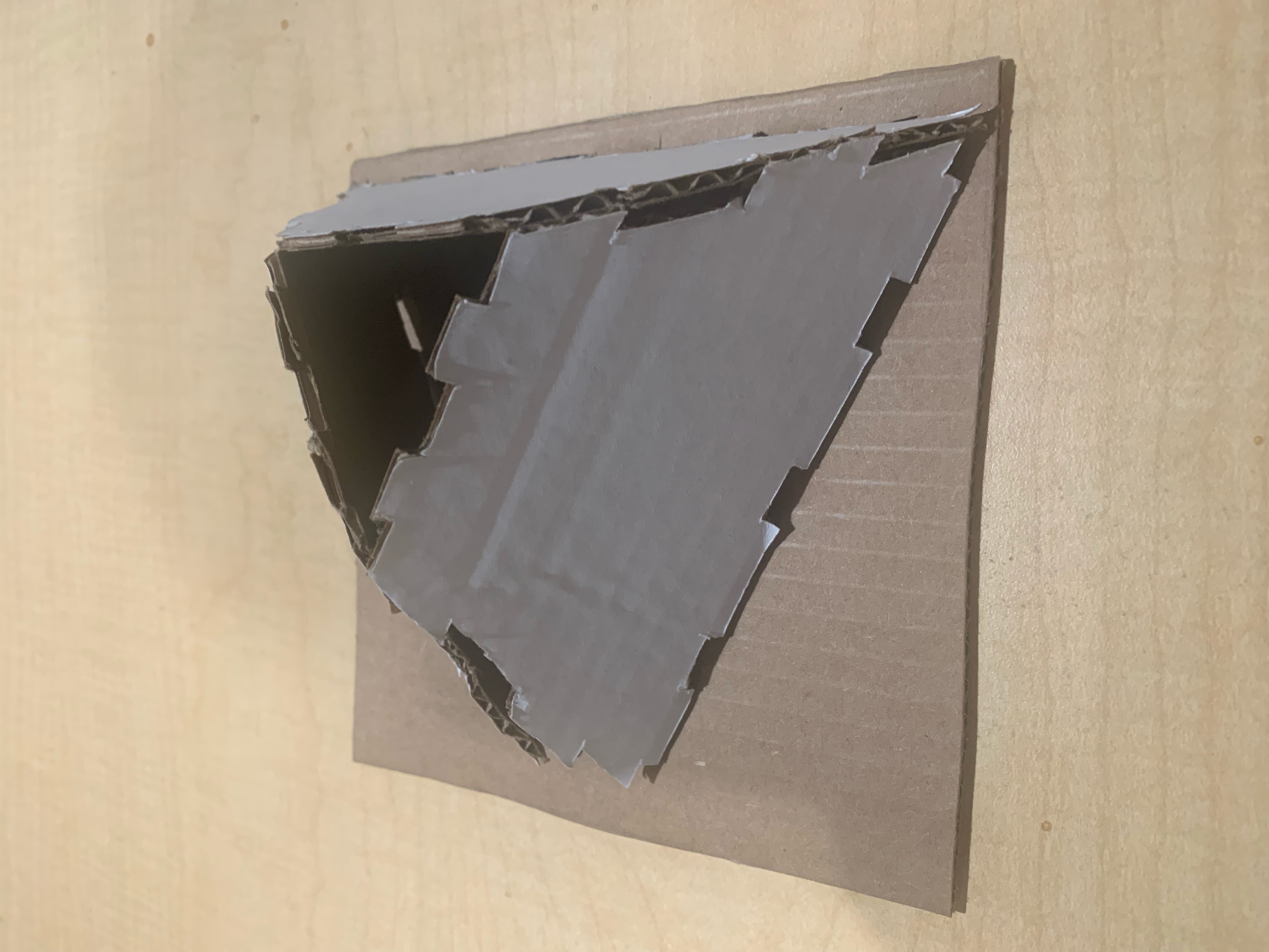
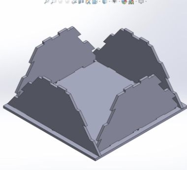
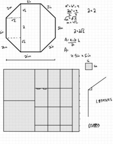
My initial instinct was to follow the non-rectangular component of the assignment by creating a truncated pyramid with trapezoidal sides and a square base, and the box sides would have been connected via tabs and nuts and screws (as pictured). In fact, my first priority was to fit the 2D faces of my box within a 10in x 12in piece of wood. I made sure to have the largest dimension of the box span 6in, and the design allowed for four unique cuts (the tops and bottoms, and two different types of sides (with alternating tabs)
I tested my prototype with scrap cardboard (saving resources), so here are my takeaways:
- I had assumed that the dimensions of the box were the only important parts, but had neglected to consider the relevance of the angles
- I had not included enough of an allowance on the base to accommodate the margin of the sides from the edge (i.e., all of my calculations on the previous slide were inaccurate)
I decided to revisit the drawing board and start from scratch. I didn’t want to completely start over, but realized quickly that calculating the correct angles of the pyramid would take too much time, and it might not be feasible given the necessary dimensions of the box.
- The trapezoidal prism would also make the process of using screws and nuts difficult because of the angled sides, so I needed a design with vertical sides
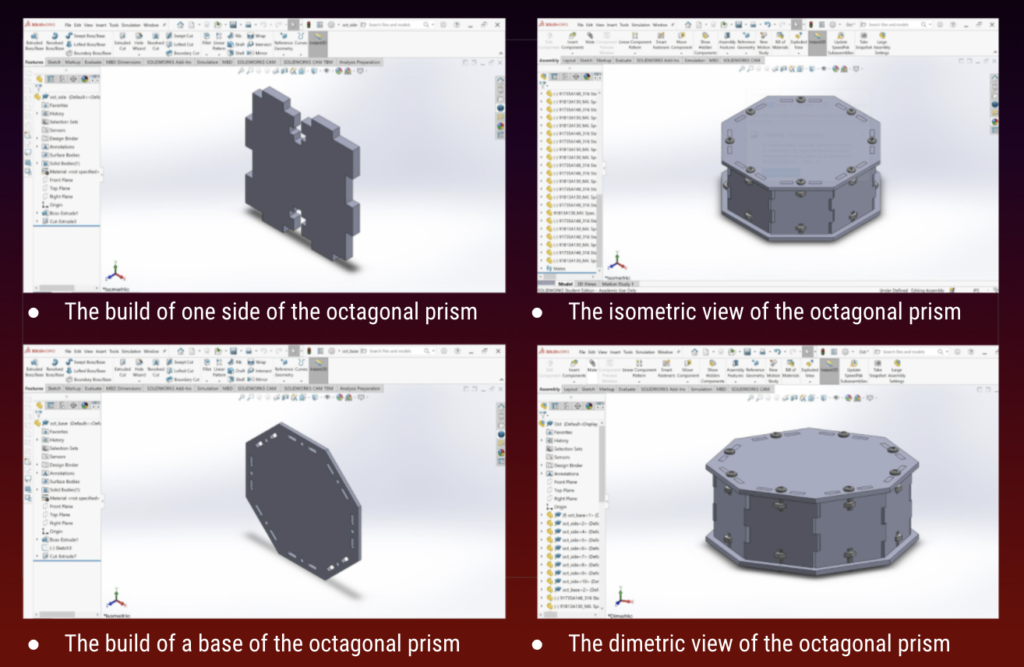
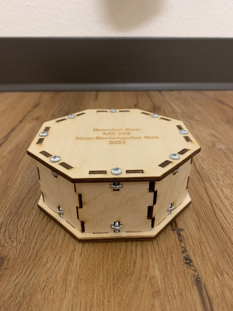
- Decided to utilize the “prism” approach, created an octagonal prism with vertical sides
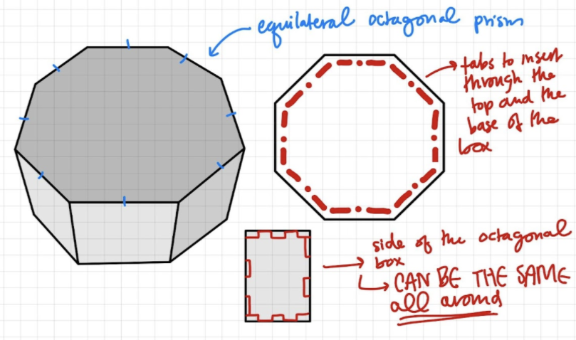
CAD Sketches in SolidWorks
I used SolidWorks to create the CAD files of my non-rectangular box, and was able to fully assemble the CAD file of my Octogonal Prism, as shown below. The CAD files include the walls, base, and top of the box as well as 16 hex nuts and 16 screws.
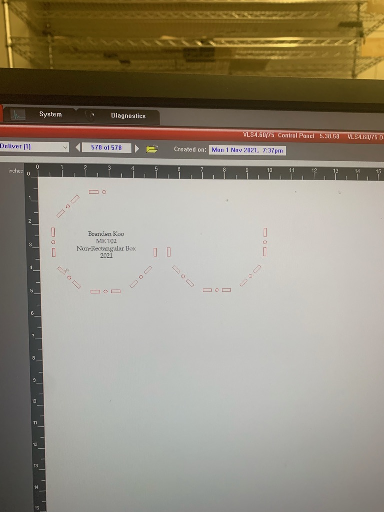
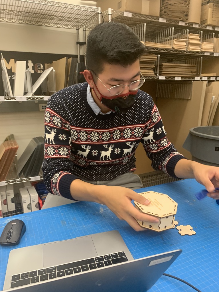
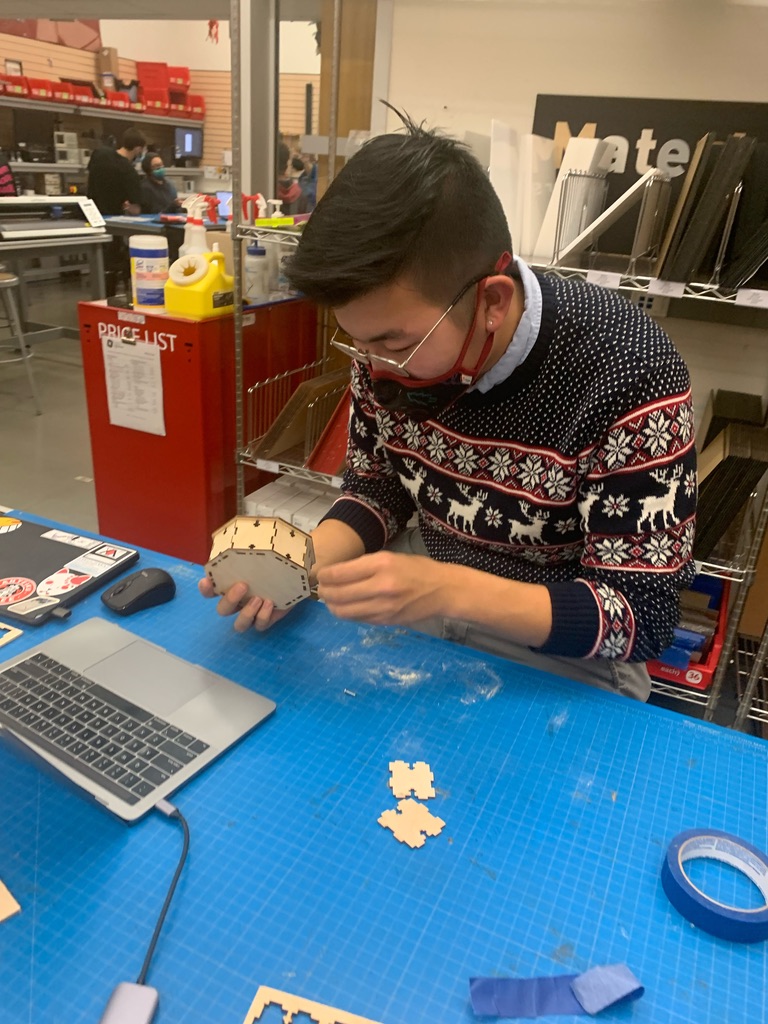
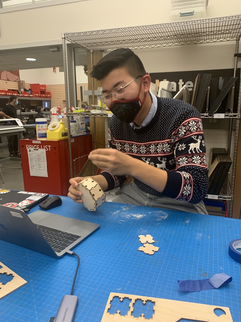
Laser-Cutting and Assembly
After my CAD file was fully assembled, I was good to start laser cutting. I transferred my CAD files to Adobe Illustrator, sent them to the laser-cutter and started the laser-cut process. The whole laser-cut process took around 15 minutes, from start to finish.
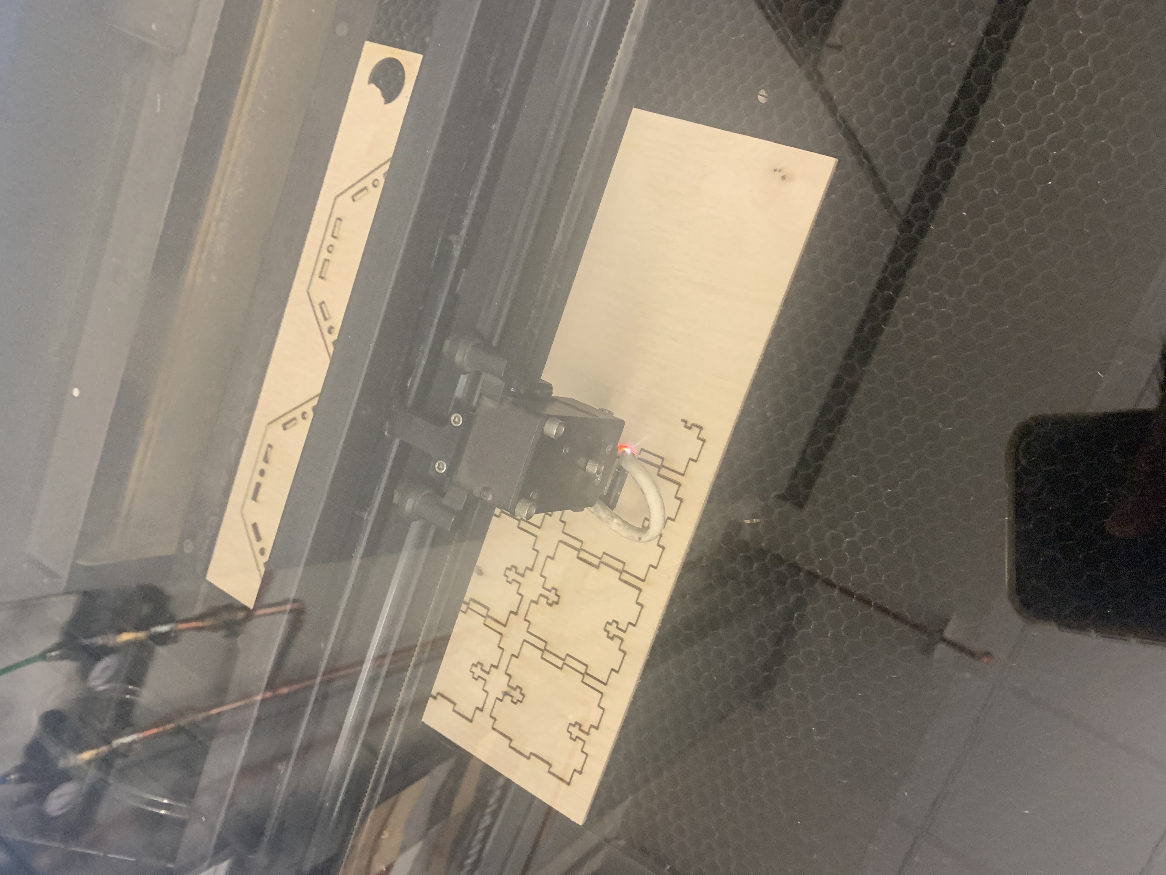
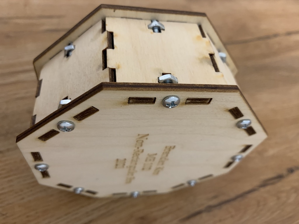
The laser-cut worked beautifully! I had a couple hiccups with the thickness of the birch plywood (the slots for the tabs were intended to accommodate a plywood of ⅛ inch thickness, but the plywood was actually measured to be 0.136 inches. However, this was no problem that sanding couldn’t rectify.
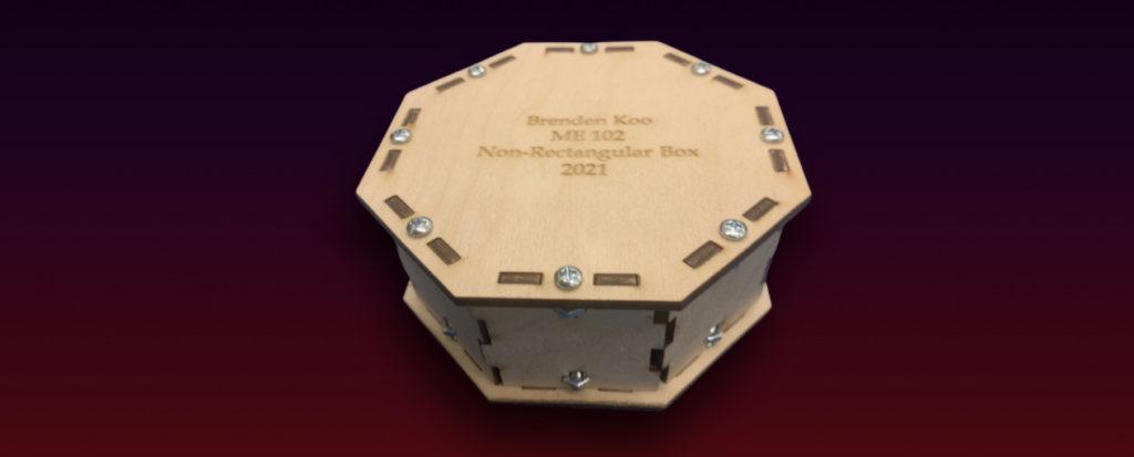
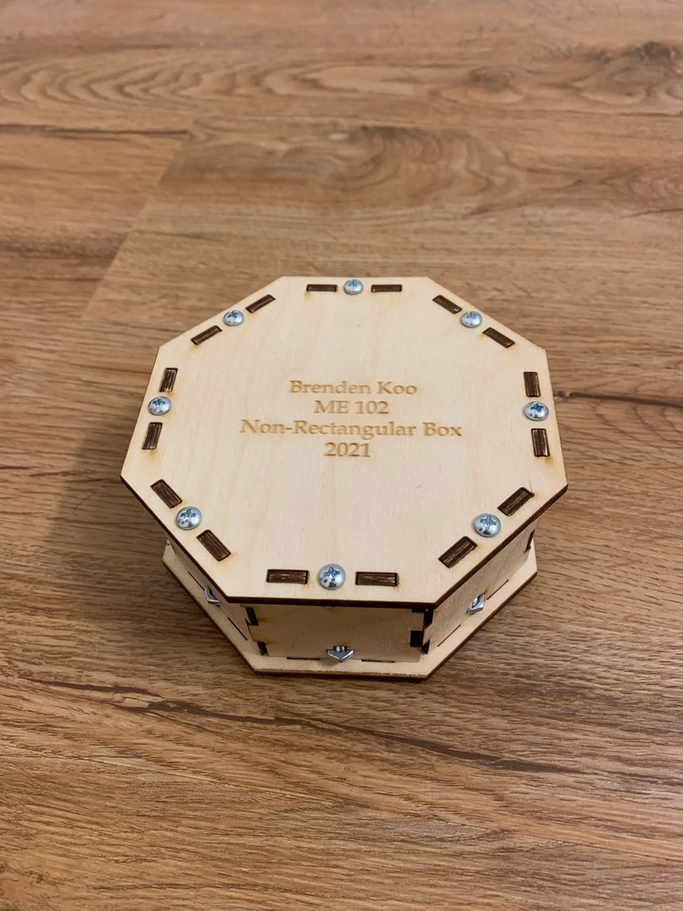
The Final Product
Analysis
- From my sketches, I learned that sometimes a design does not need to be overly complicated, and simplicity often flourishes
- From designing the CAD file of the truncated square pyramid, I realized that my calculations for the angles and sides of the model were not as fully defined as I thought they would be → led to misalignment of the sides
- The slanted sides of the model would require a “slanted screw/nut joint” (not possible with the resources provided in Room 36) or more complex calculations to determine the inset of the screw/nut placement in the model so as to align a vertical screw with an angled box face
- The CAD file of the octogonal prism was a lot simpler, and it came together a lot quicker in SolidWorks
- When the pieces were laser-cut, the pieces of birch plywood were actually around 0.136 inch thick instead of ⅛ inch, so that led to some discrepancies in the sizing
- The sides of the box were all perfectly fitted, so there was not enough of a tolerance for the walls to come together
- I ended up resizing just one of the sides to create an allowance for the tabs to fit together
- The 16 nuts/screws and all of the interlocking tabs might have been a bit redundant in my design, so I could have advanced it by minimizing the joints I used
Reflection
I learned from this experience that I don’t necessarily need to construct my box in such a complex manner. This is evident not only in my initial prototypes/designs but also in how many joints/fasteners I had utilized in constructing even my finalized non-rectangular box. I realized that as a designer, I need not opt for the most complicated designs, and sometimes the simpler and more straightforward options are equally successful and more efficient.
However, I will acknowledge that my decisions to step outside of the metaphysical “box” did allow me to experiment with different approaches, try out different configurations for the box, and ultimately fail before realizing that I needed to revisit the drawing board and think through the entire process of constructing the box, rather than thinking about it in a step-by-step fashion.
My biggest challenge with the construction of this box was with the calculations and allowances of the kerf when laser-cutting, as I initially somewhat inaccurately accounted for board thickness discrepancies as well as the seam allowance of interlocking tabs. This made the physical assembly of my box a little bit more difficult than I had anticipated. I overcame this challenge by using a little bit more patience in assembling the box, as opposed to utilizing brute force (which would have broken my box).