
This project was for my Design for Additive Manufacturing Class in the Winter of 2023. This project allowed me to strengthen my CAD, Finite-Element Analysis, and Shape Optimization Modeling skills, all in AutoCAD Fusion 360.
Check out my full final report here:
Check out my Full Portfolio for the course here:
Project Interpretation
The prompt is fairly open-ended, and I initially opted for the route of redesigning a part by leveraging AM capabilities. I wanted to utilize shape optimization simulations to redesign bike-mounted water bottle holders. Simultaneously, my biggest qualm with bike-mounted water bottle holders is that those on the market (and currently mounted on my bicycle) are typically fixed for a specific size. I wanted to design a water bottle holder that is adjustable or accommodates a wide range of sizes.
Mechanical Function
The core function of my design is pretty simple–to allow people who bike to carry their water bottles with them as they go. Specifically, my design would be catered to bikers who opt for larger water bottles than the “standard size” single-use disposable bottles.
I’mma Buy You a Drank.
Then I’mma take you home with me
T-Pain
Ideation
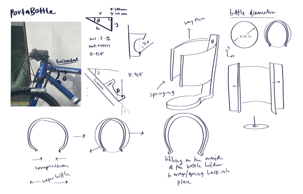
Initial Sketches
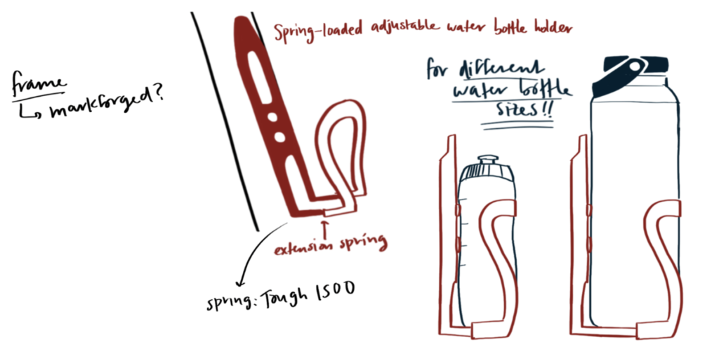
My initial idea was a hybrid between an adjustable water bottle holder and something designed with algorithmic modeling.
I realized that ultimately, it would be difficult to design something that is both adjustable and algorithmically modeled within the scope of the project. I understood that I could separate the design into parts and tackle each part differently, but in the interest of time, I opted to solve each problem separately and choose a model to pursue before I printed.
Solution 1: Shape Optimization
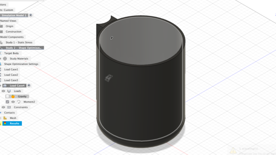
Shape Optimized CAD 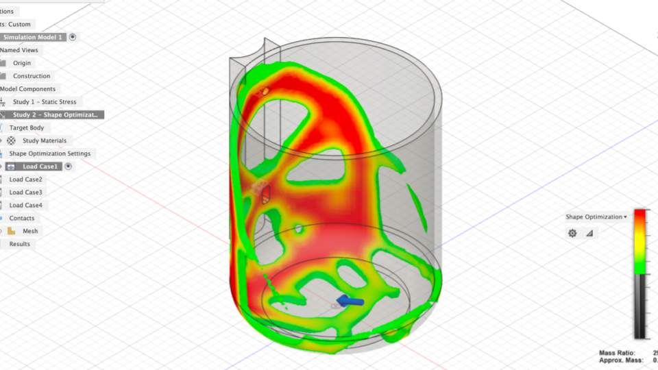
Shape Optimized CAD 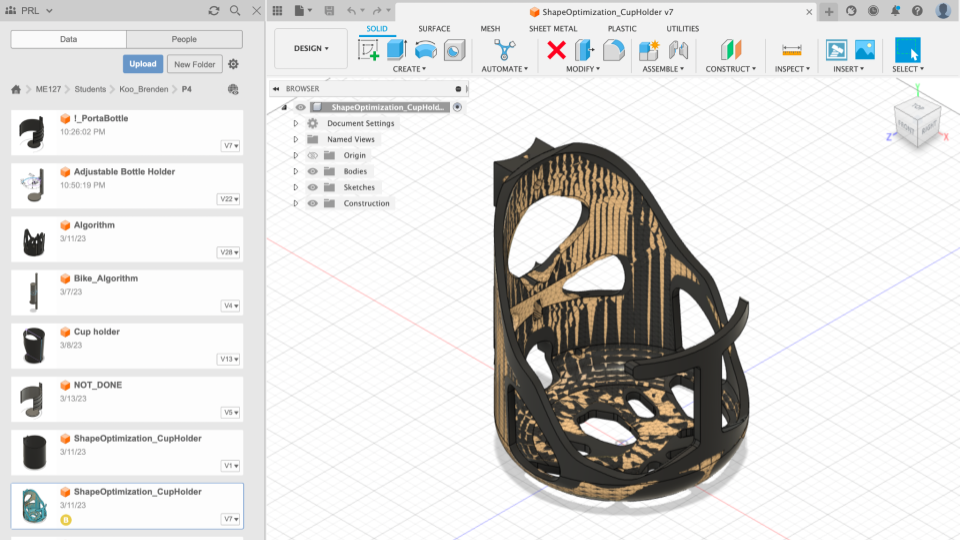
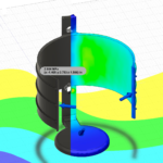
I created a model of a cylindrical shell with the same diameter as my water bottle. I constrained each of the load cases with fixed connections at the holes and applied the following load cases:
- 33.362 N load acting on the base face at a 37-degree angle
- 33.362 N load acting on the base face at a 37-degree angle and 5 N load acting normal to the cylindrical walls
- Misuse Case: 33.362 N load acting on the base face at a 37-degree angle and 5 N load acting down on the cylindrical rim
- 5 Nm moment acting on the upper cylindrical hole
Solution 1 Result
- The shape optimization simulation yielded the following result, which I promoted to the design workspace
- I cut-extruded the model to resemble the general model created by the simulation
Solution 2: Adjustable Design
I opt to pursue a design that accommodates larger water bottles, using a spring-loaded mechanism.
At this point, I knew that I wanted to pursue a design that accommodates varying water bottle sizes, including the 32oz water bottles I typically drink from.
Re-thinking the prompt, I am still trying to take advantage of the additive manufacturing capabilities, gaining more hands-on experience with AM, and exploring material properties as they relate to flexibility and springiness.
Iteration
Materials Selection – Tough 1500
In choosing a material with flexibility and durability, I was torn between Durable and Tough 1500. Durable, as the name suggests, has a higher pliability rating than Tough 1500. However, Tough 1500 has a faster spring back, which would be necessary for the “snap” feature that I would want in my design. Ultimately, I deduced that Tough 1500 and Durable were similar enough in pliability (the design need not be so flexible, just enough to deform slightly)
Using Tough 1500, I knew that I needed to be able to have a design that would flex and bend repeatedly, all while being durable enough to hold my water bottle in place
In order to use Tough 1500 in my CAD (as the material is unavailable as a pre-set) I selected and edited Tough 2000 (in the same material family) and edited certain material properties with Tough 1500 specifications.
CAD Models
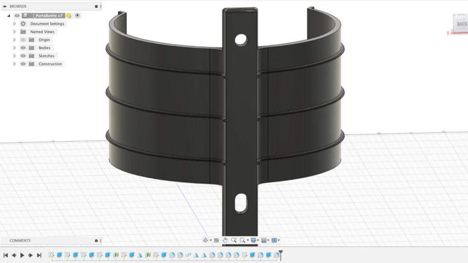
Portabottle CAD 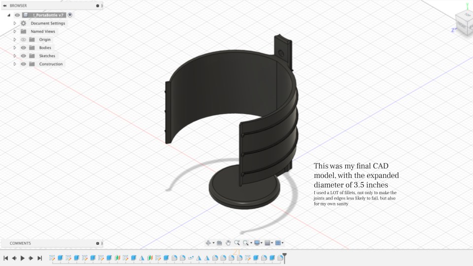
Portabottle CAD
Simulations
A large part of this project was focused on CAD simulations, and ensuring that the design I create is able to withstand the necessary forces of interfacing with a water bottle, as well as unexpected forces associated with riding a bicycle.
The CAD simulations implemented the following load cases (in addition to being constrained at the holes):
- Load Case 1: 15 lb-force loads acting on the outer lips and a 3.5 lb-force load acting on the top face of base
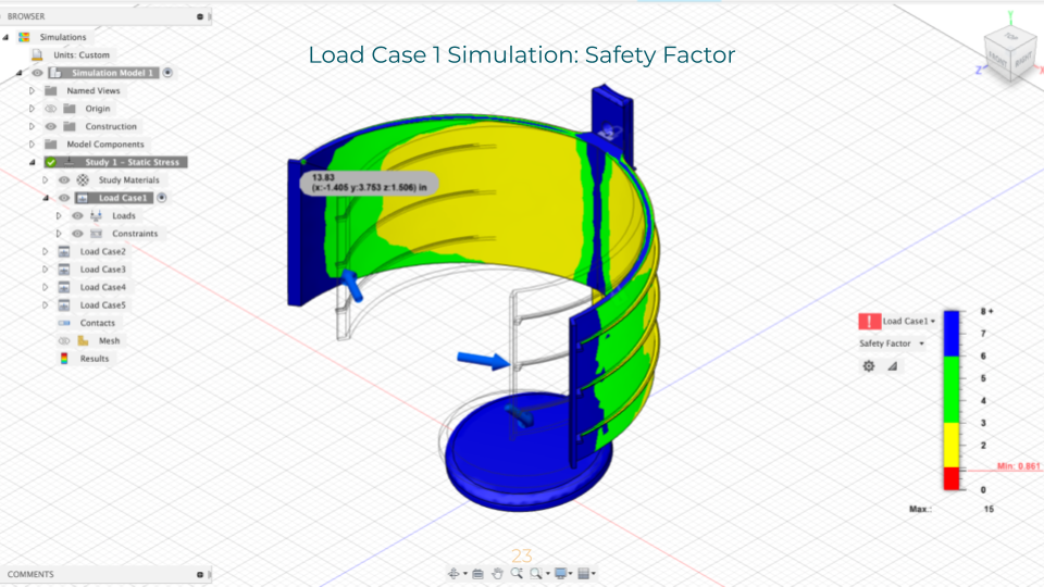
Load 1 Simulation: Safety Factor 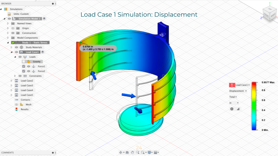
Load 1 Simulation: Displacement
- Load Case 2: Misuse case: 15 lb-force load acting on the upper rim and a 3.5 lb-force load acting on the base
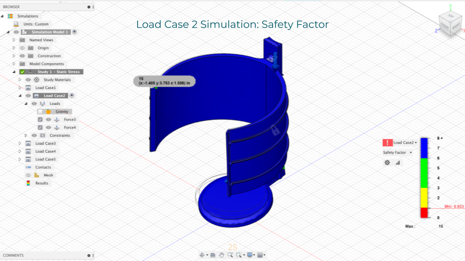
Load 2 Simulation: Safety Factor 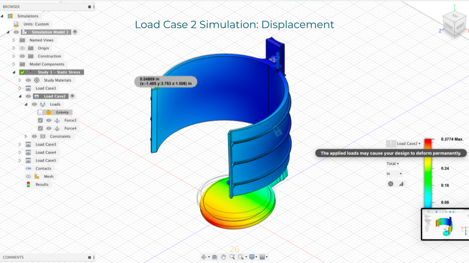
Load 2 Simulation: Displacement
- Load Case 3: Misuse case: 3 lb-force load acting on the bottom face of the base
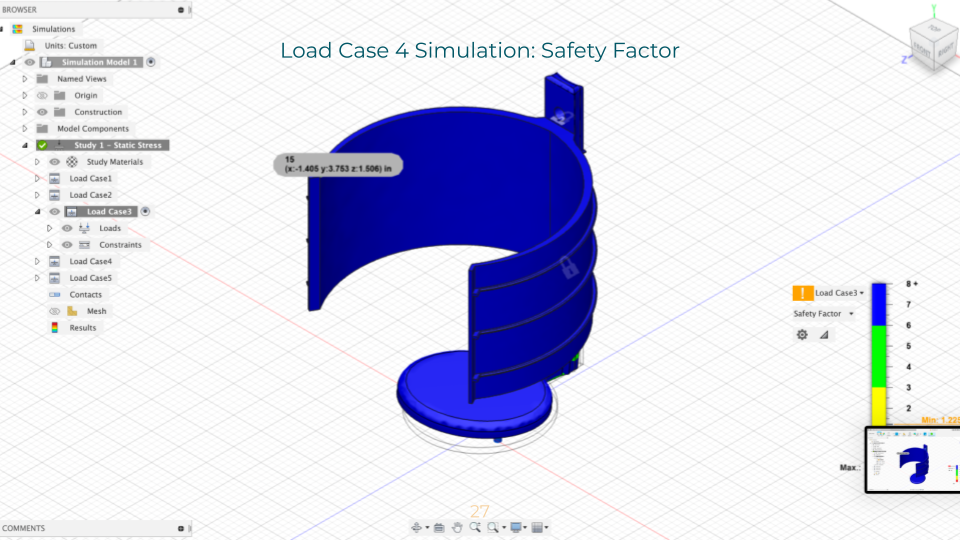
Load 3 Simulation: Safety Factor 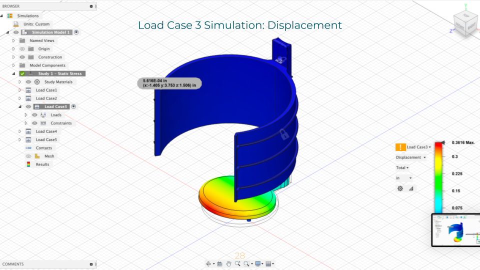
Load 3 Simulation: Displacement
- Load Case 4: Misuse case: 5 lb-force loads acting normal to the external faces of the holder
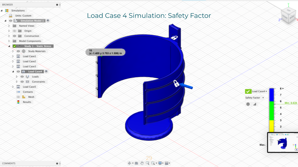
Load 4 Simulation: Safety Factor 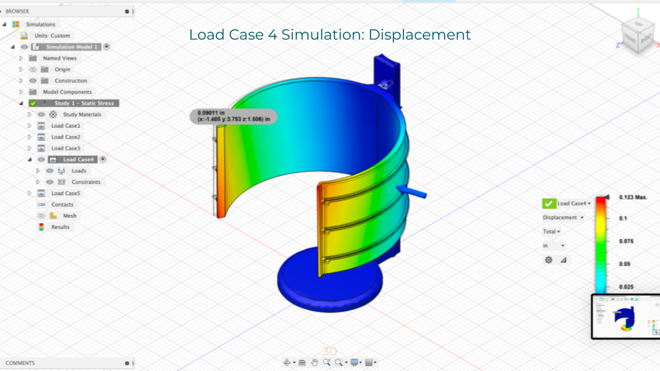
Load 4 Simulation: Displacement
- Load Case 5: 10 Nm moment acting on the cylindrical hole
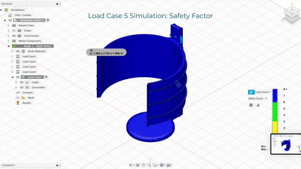
Load 5 Simulation: Safety Factor 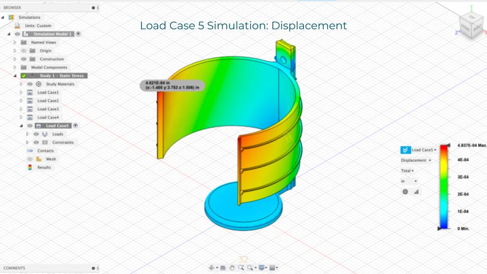
Load 5 Simulation: Displacement
Simulation Analysis
Essentially, the simulation demonstrated that the design was strong enough to perform as necessary! The first two load cases, however, failed with a safety factor of 0.86 and 0.93, respectively. Following a discussion with numerous CAs, I decided that the failure points (at the external ribs and internal faces of the lower hole) were small enough to be neglected.
Final Prototype
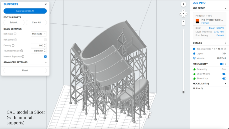
FormLabs Model Print 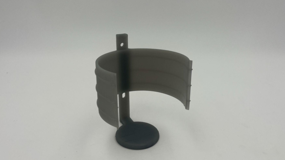
PortaBottle
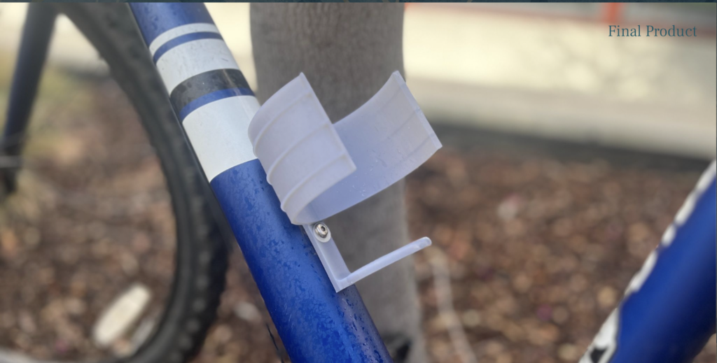
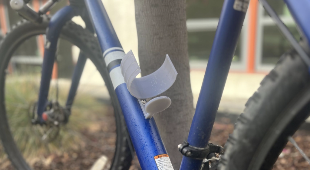
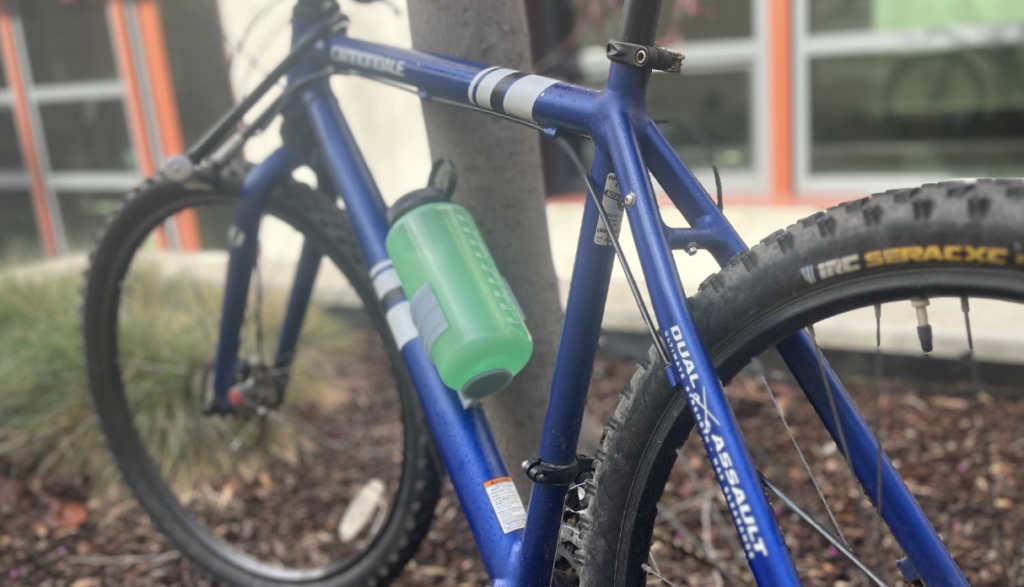
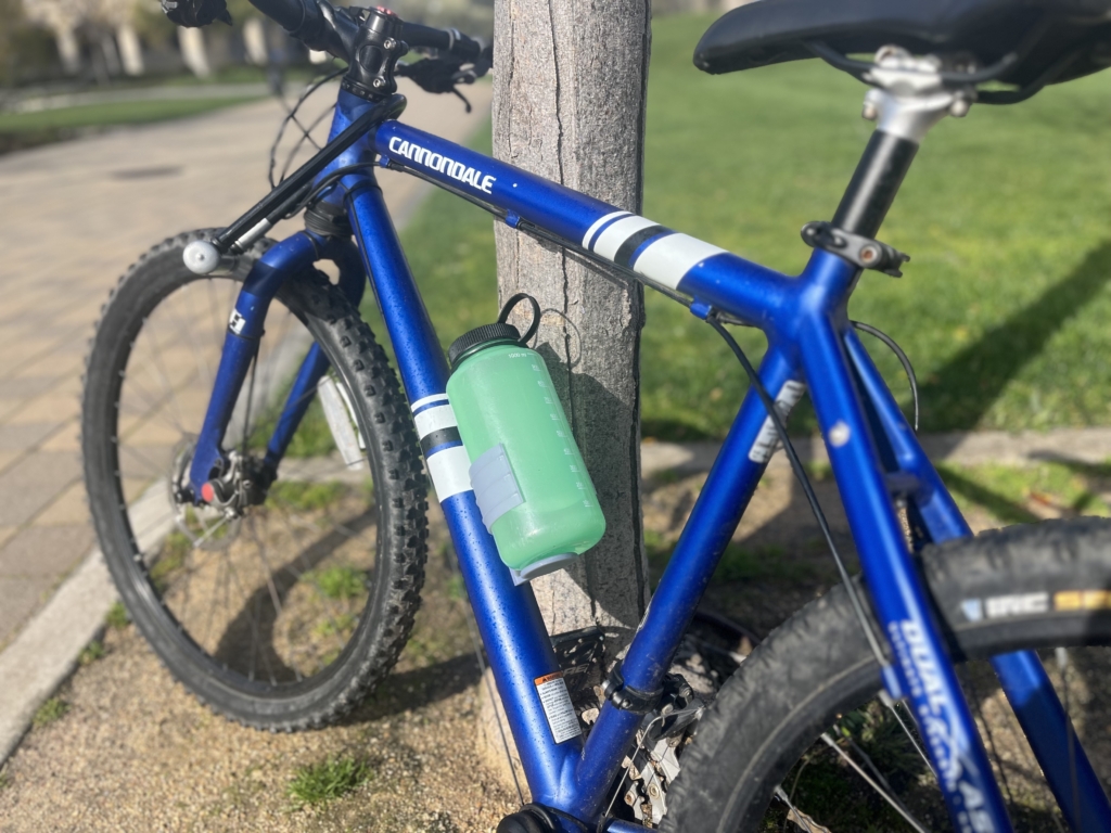
Design in Action!
Video
Final Reflection
Analysis
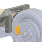
My design was successful! The bottle holder mounts to my bicycle frame with no problem, and it seems more than capable of carrying my 32oz water bottle. The bottle slips in and out of the holder with ease and satisfaction–the holder is flexible enough to widen to the diameter of the bottle, but snaps back into place to the point where the bottle is nicely constrained, even with a significant amount of movement or inertia. When biking around, the bottle is nicely secured. If I had more time, I would consider how I could either make the design more adjustable to be capable of holding smaller bottles (but who drinks out of those?) or more mass efficient using algorithmic modeling–or who knows, maybe even both. However, as I am faithful to my 32oz water bottles, I am more than satisfied with my current design.
Reflection
I am more than pleased with the outcome of my final project, as I was able to imbue my academic learnings with a real-world purpose. Although my final outcome deviated from my initial ideation, I was able to explore the iterative process and determine a solution that was much more suitable for my intended outcome. I appreciate the help of the CAs and Dan who have–once again–provided me with valuable advice on how to elevate my design, approach the prompt from different perspectives, and continue pushing forward in the face of challenges. Admittedly, even though I had thought my initial idea was well-scoped, I found that it was, yet again, out of scope for the time frame of the assignment. Moving forward, I will attempt to have a better understanding of project timelines to scope my project properly from the start. Furthermore, in the future, I will take care to wash and cure my 3D-printed part BEFORE I remove the supports, as that evidently makes a big difference.
Bill of Materials
| Material | Cost |
| Test Prototype 1 | $16.89 |
| Test Prototypes 2-4 | $9.36 ea (x3) |
| Final Prototype | $17.28 |
| ¼” Flat Nylon Washer, 95606A130 | $0.20 ea (x2) |
| Total | $62.46 |
Design Time Estimate: 11 hours
Print Time Estimate: ~43.5