This project was completed in conjunction with my Mechanical Engineering teammates: Addie Stonecipher (Stanford ’23), Brandon Briones (Stanford ’23), and Ian Gunther (Stanford ’23). We completed this project for our ME104: Mechanical Systems Design course that we took in the Spring Quarter of 2022. We were named Tony’s Tigers, in loving tribute to our Teaching Aide, Tony Chen.
Summary
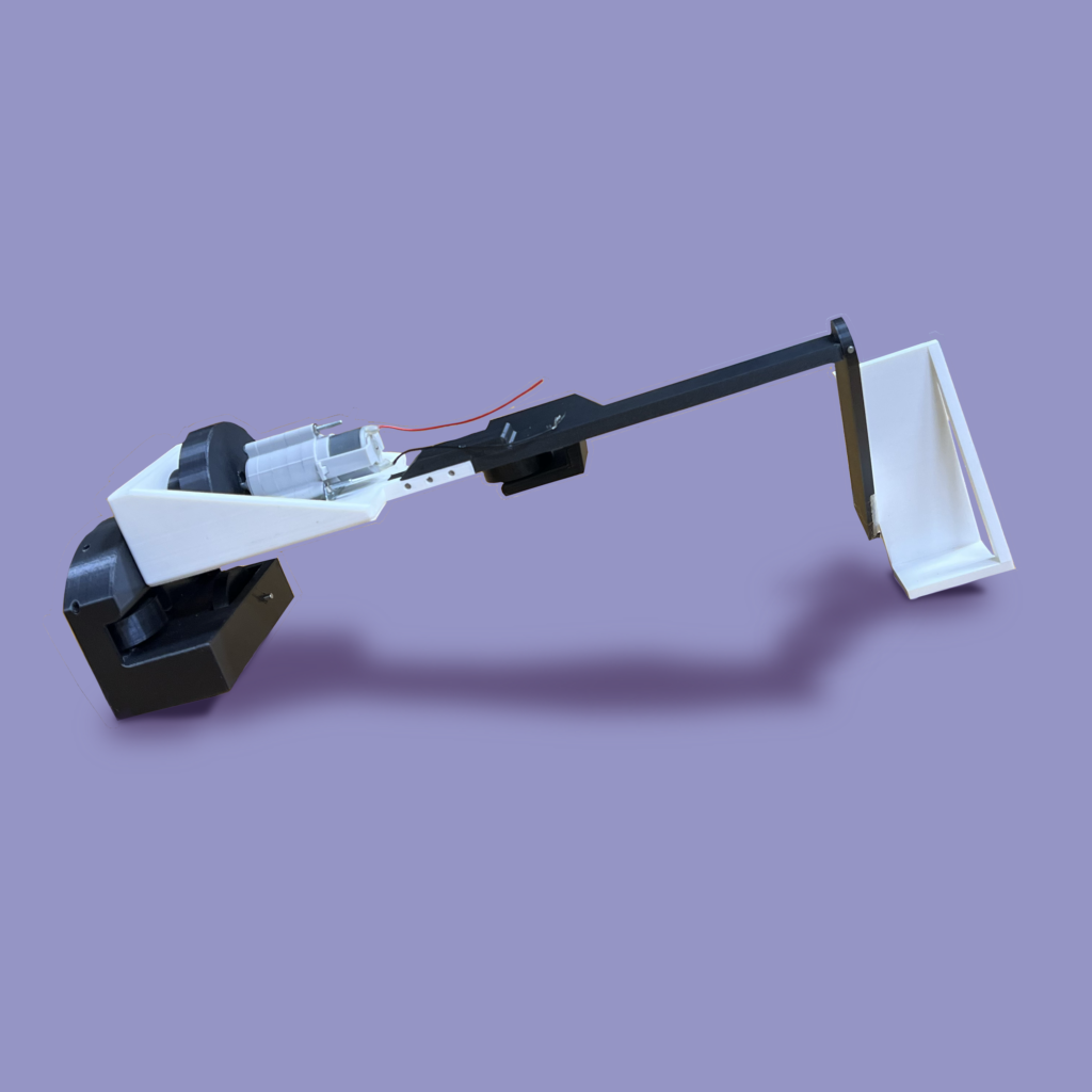
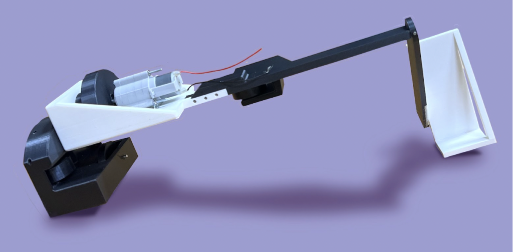
The robot was designed to carry a 1-kg payload one meter up the I-Beam at an angle of 41.7° as fast as possible while maintaining the payload 10.5 inches from the center of the I-Beam. The robot utilizes a simple design of a chassis, one driving wheel, and three driven wheels to constrain the robot around the beam, as well as a horizontal and vertical beam to hold the payload in the specified orientation. The normal force on the driving wheel was determined using FBDs. Given material constraints, the normal force required to sustain the coefficient of friction of 0.1 was reached by utilizing an increased lever arm from the payload to the driving wheel. Four wheels were used to counteract the moment on the driving wheel created by the payload in two planes and achieve static equilibrium. This was achieved by including the driving wheel on top of the I-Beam, the bottom wheel under the lip, and two side wheels offset from the horizontal axis of the robot to act as constraints. Stress analysis and FEA were used to determine the dimensions of the top beam and side beam to prevent breaking, reduce deflection, and increase mass efficiency. To reduce the deflection and stress of the top beam depicted by FEA, the thickness of the top beam was increased above and around the connection between the top beam and the chassis. The side beam was designed to hang vertically to the ground to reduce torsion on the connection point between the top and side beam, with a “cradle” attachment to keep the payload in the specified orientation. The cradle was positioned outside of the vertical beam to reduce the length, and therefore deflection, of the top beam by reducing the maximum applied moment. Fixed connections between the side beam, top beam, chassis, and side housing were created using square pegs and pin connections in order to constrain all degrees of freedom. In order to increase power, and therefore reduce climbing time, transmission analysis was performed to determine the torque at max power. This value for torque was used to design the final radius of the driving wheel at 1.25 inches.
Free-Body Diagrams:
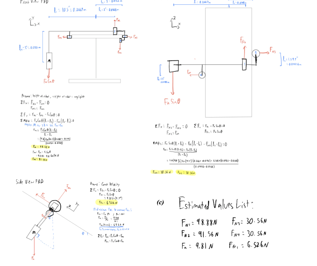
For each FBD, acceleration was assumed to be constant, and the height and weight of the robot were assumed to be negligible. For the moment balance in the front view FBD, moments from wheels 3 and 4 were neglected because FN3 = FN4 and they are at equal vertical distances from wheel 2.
Transmission Analysis:
Set-Point Approach
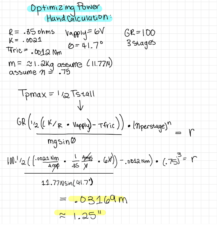
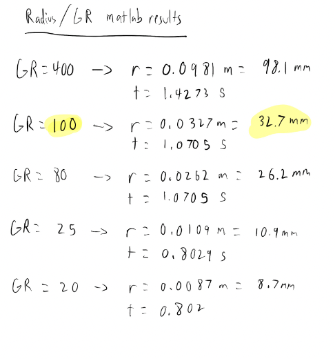
Time is inversely proportional to power, so in order to decrease the time it takes for the robot to climb the beam, the torque at max power was calculated. To calculate this torque, an equation was derived that is equal to ½ the torque when the motor is stalled. This equation was calculated by hand and incorporated into a matlab script to estimate various combinations of the radius of the wheel and gear ratio that would allow the robot to climb the beam at maximum power. The voltage was capped at 6 Volts for this project, and since P = IV, the maximum value of 6 Volts was applied in order to maximize power. The mass of the entire robot including the payload was assumed to be 1.2kg for this analysis. After the hand calculation was done, a radius of .03169m was found using a gear ratio of 100:1. The Matlab script was run to derive different radii and fastest times given various gear ratios. The radius and gear ratio that were found with the hand calculations were confirmed, as having a 3 stage gearbox was calculated to be faster than having a 4 stage gearbox while still providing sufficient torque, and the calculated radius was a reasonable size compared to the physical size of the motor.
Set-Point Diagram
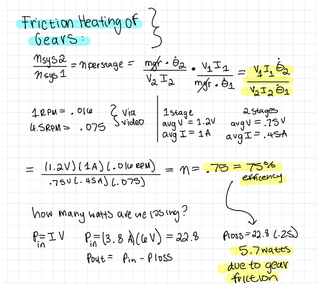
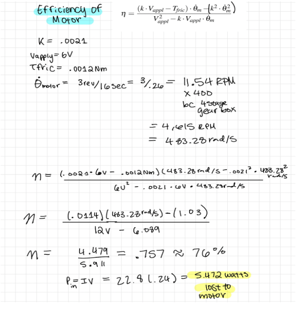
Power Flow
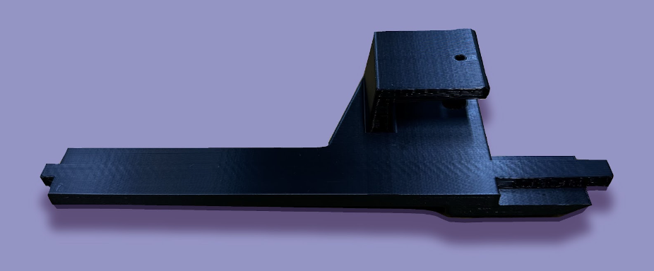
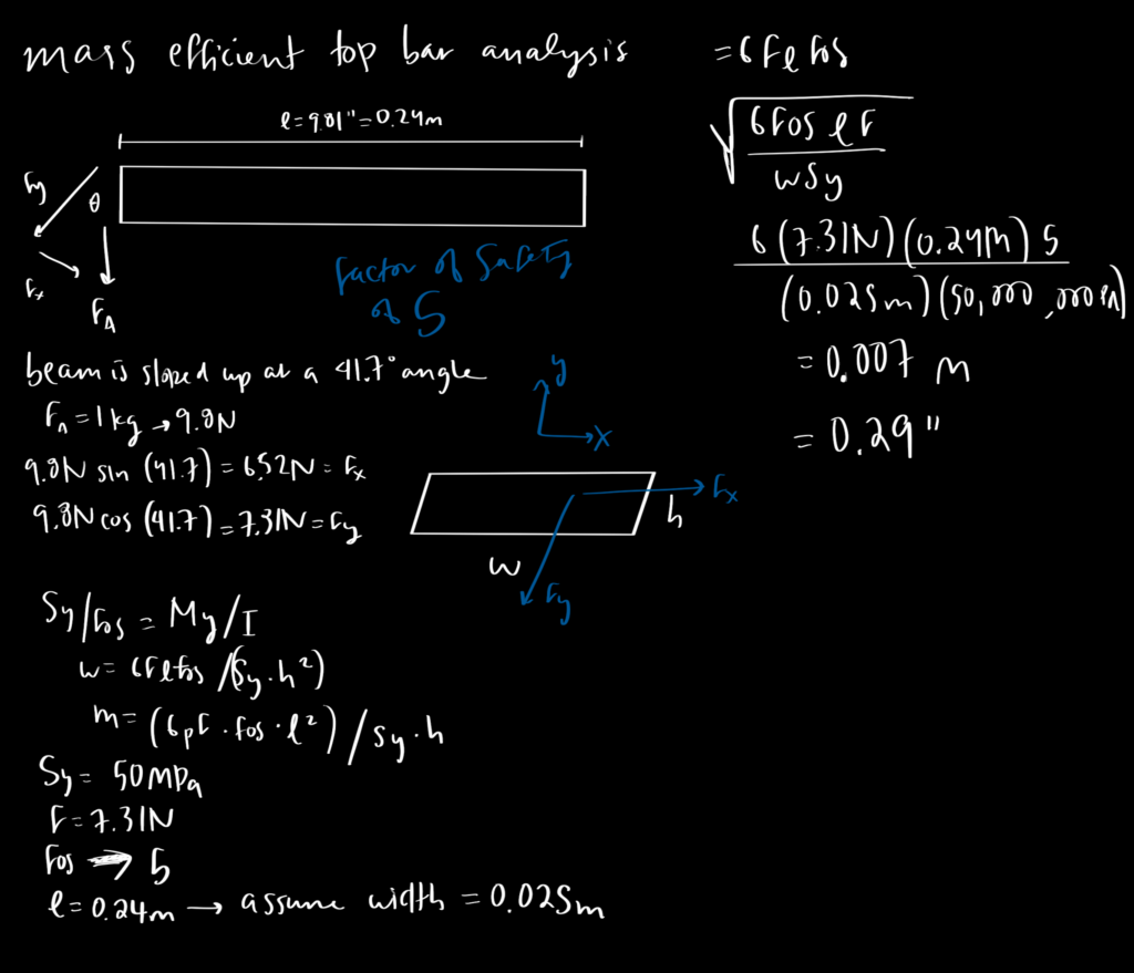
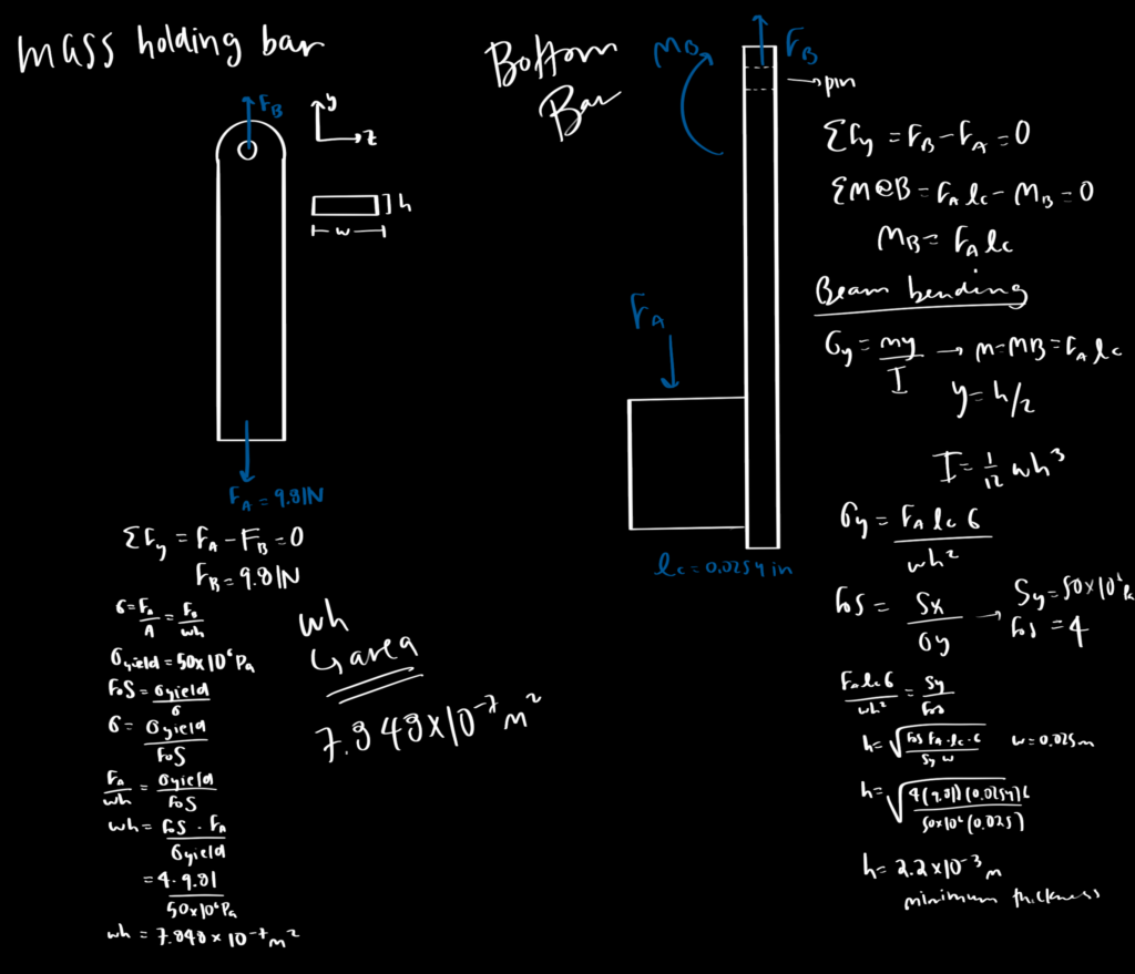
Component Analysis 1: Top Bar
The top bar of the robot is fixed on one end and supports the payload on the other, increasing the susceptibility to bending. The top bar has a length of 0.24m and is assumed to have a width of 0.025m. The bending analysis demonstrated that the expected height of the top bar was to be 0.007m, with a safety factor of 5. The right end of the top bar has three pin connections, fixing it rigidly to the motor housing. The FEA illustrates that this end of the bar is the most stressed area of the component. In order to prevent deflection here, this part of the bar has a height twice the size of the rest of the component.
The left end of the bar has a square peg and shaft that goes through the sidebar of the robot. The square peg and shaft restrict all degrees of freedom, prohibiting the payload from swinging or falling.
BOTEA of the Top Bar
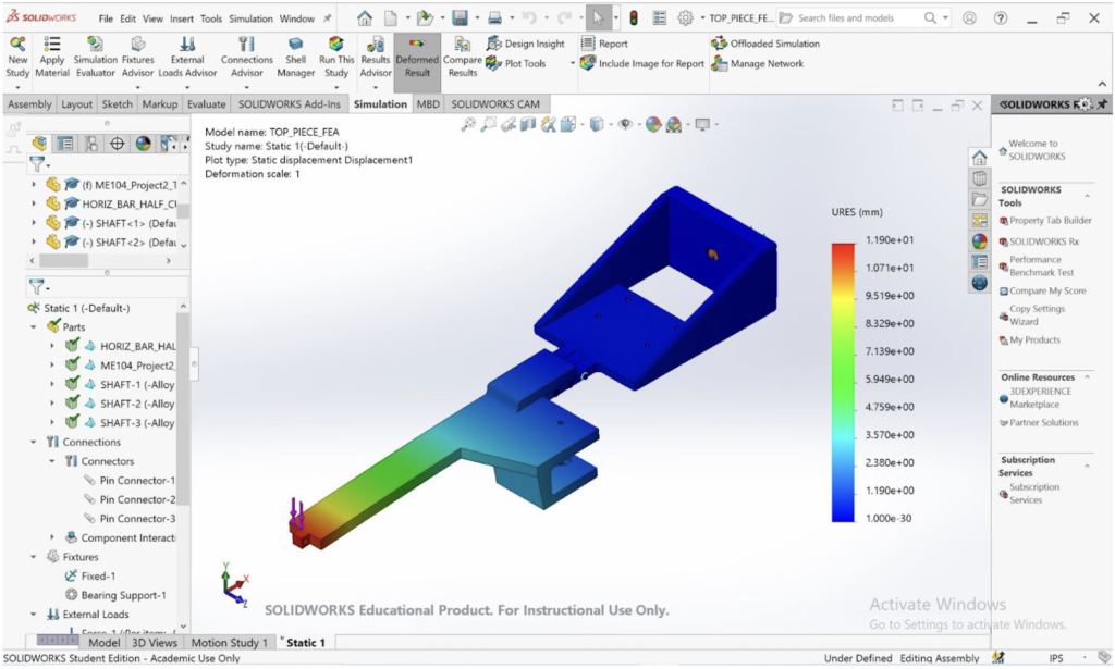
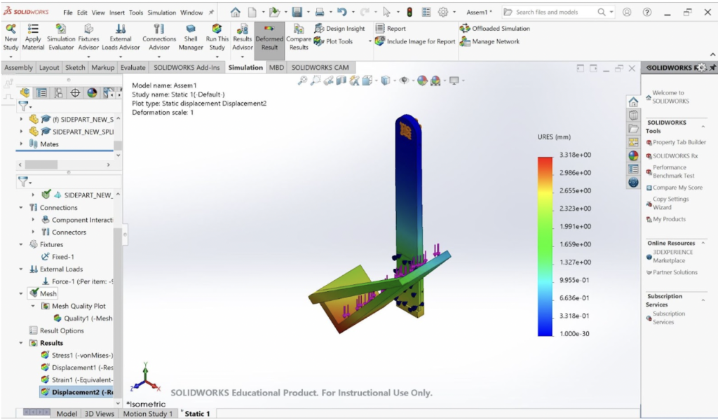
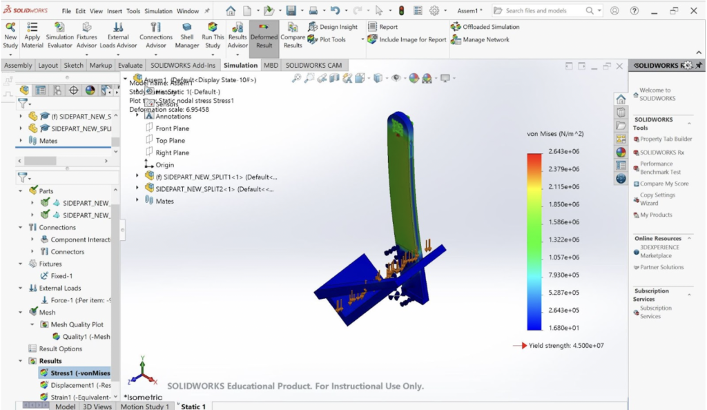
FEA Analysis of the Top Bar
In the analysis of the top bar, the FEA considers the reactions of the chassis and the horizontal bar together, to account for the forces acting on the part via the driving wheel. The load acting on the shaft and bearing connecting the driving wheel to the chassis is half of the normal force acting on the driving wheel or 49.44N, and each of the four holes that constrain the motor to the chassis bears an ⅛ of the normal force or 12.36N. There is a 9.81N load acting on the end of the top bar, simulating the weight of the payload. The horizontal bar and the chassis are connected via 3-pin connections, and the square peg of the chassis–away from the horizontal bar–is constrained via fixtures to simulate the connection to the side housing. Where the shaft and the bearing connect the driving wheel to the chassis, the FEA model implements a bearing fixture.
The stress analysis demonstrates that the highest points of stress are at the pin connections between the chassis and the horizontal bar. The top bar is doubled in thickness at this point of concern, so as to accommodate this stress region. This increased thickness also increases rigidity and ultimately decreases deflection.
Furthermore, the displacement analysis of the top bar and the chassis demonstrates deflection at the end of the shaft close to the pin connection between the top and sidebars. The height of 0.007m is set to accommodate the potential deflection of the top bar. With this design parameter, the top bar is expected to only deflect 0.0119m at the greatest point of displacement.
Component Analysis 2: The Side Bar
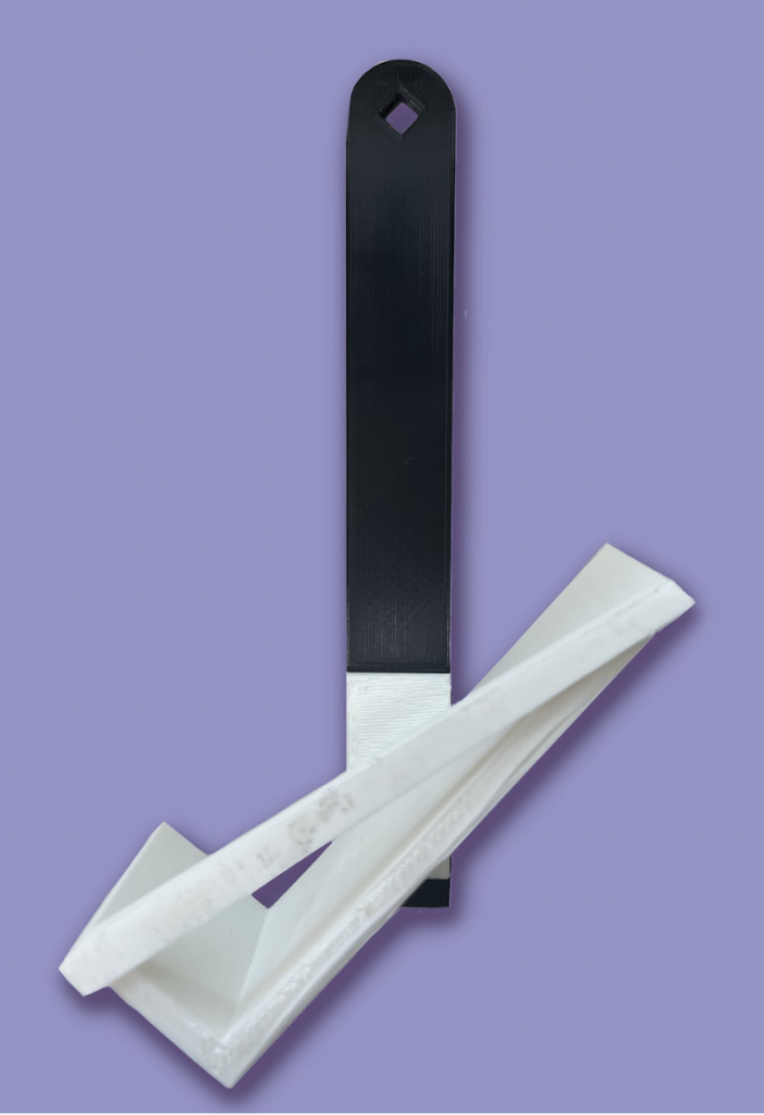
The sidebar was designed as two pieces, fixed together using hot glue: the vertical bar that implements a square slot to conjoin with the top bar, and the angled cradle to hold the payload. The slot for the top bar accounts for a square peg and a pin connection so that the sidebar could be positioned vertically, to reduce torsion on the connection point and to reduce swinging. Increased torsion would increase the stress and deflection of the sidebar, too much of which would result in interference between the top bar and the I-beam, which would reduce the normal force on the driving wheel. Swinging would decrease the stability of the robot, while greatly impacting the normal force on the driving wheel. To account for the assignment requirements to position the payload properly with the centroid of the I-beam, a “cradle” attachment physically constrains the payload at the proper angle. The “cradle” is positioned on the outward-facing side of the sidebar, in order to reduce the length of–and ultimately possible deflection of–the top bar. The maximum possible moment created by the horizontally-displaced payload is therefore decreased, as a result of the shortened top bar. To follow the existing geometry of the top bar, the width of the sidebar is selected to be 0.025m and the thickness of the bar is then calculated to be 2.2 * 10-3m with a factor of safety of 4.
BOTEA of the Sidebar
FEA of the Sidebar
An FEA was conducted on the part by fixing the square peg as it is restricted in all degrees of freedom. A force of 9.81 Newtons was vertically applied on the surface of the cradle. Our FEA results show that our part is unlikely to break during the applied load, and will slightly deform towards the I-beam. The FEA results show the highest stress concentrations are around 90° angle of the cradle. However, even the highest stresses of the part are well under the yield stress of PLA. This is by design, as a high safety factor of four was chosen to ensure that the part does not break if the mass is bouncing or is experiencing other complications.
The part was designed to have a vertical sidebar with the cradle angled at 41.7°, the angle required to hold the payload. This was in order to reduce the moment the sidebar applies to the top bar when it is angled. By allowing the bar to remain vertical, it reduces the deflection and stress, resulting in a more efficient part. The FEA supports this idea by showing the minimal stress experienced by the sidebar. However, the sharp angle in the cradle is experiencing a higher stress, so a crossbar was added and the thickness of the cradle was increased such that the stress does not exceed 12.5 MPa.
Due to our high factor of safety for this part, it is expected to not cause any issues for the system. Empirically this was true and the part functioned as expected.
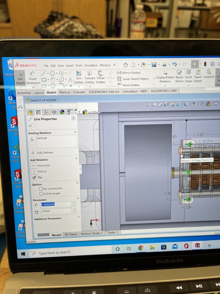
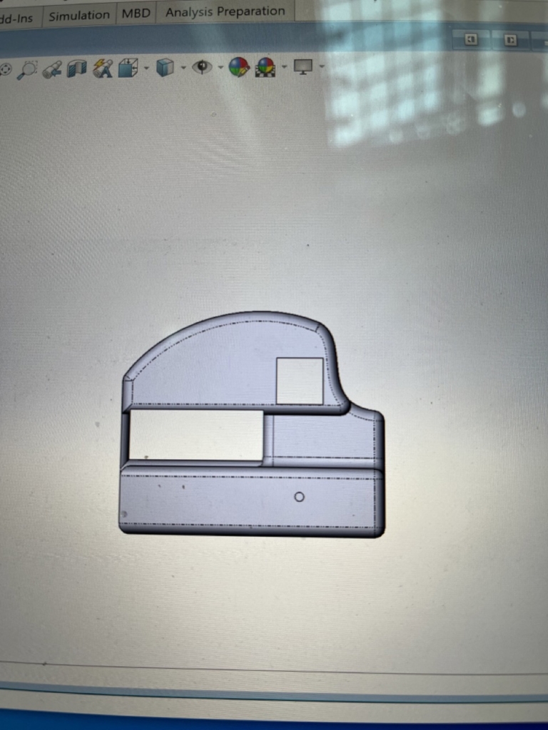
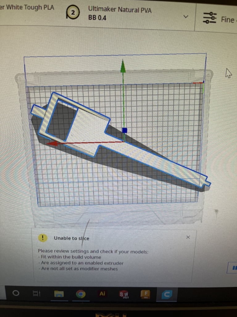
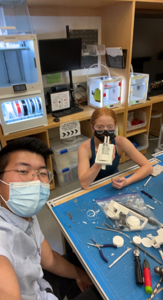
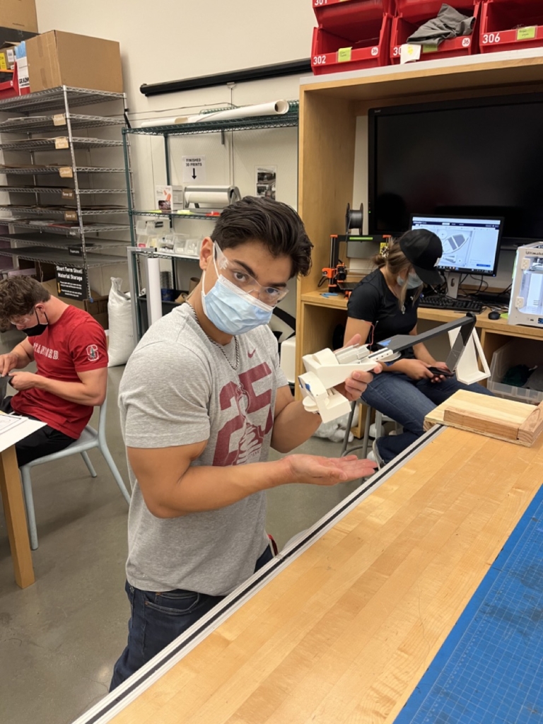
Process Photos
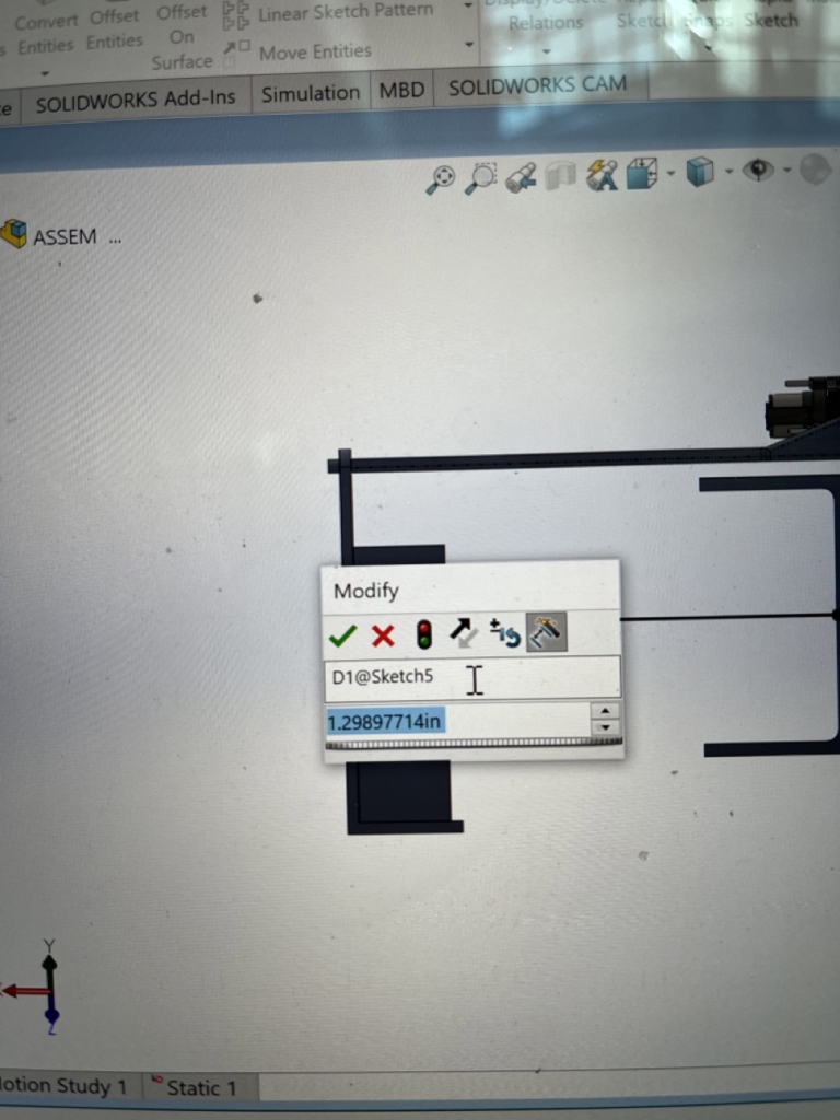
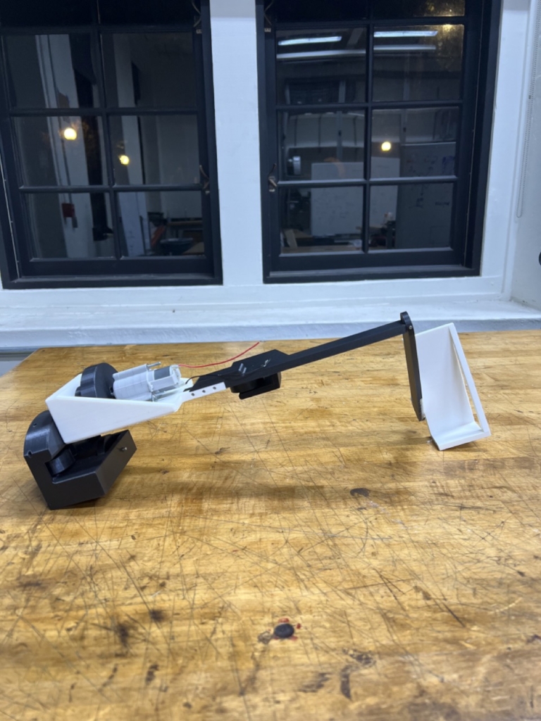
Performance
As the above video demonstrates, our robot successfully climbed the designated 41.7° I-Beam with a 1kg load of aluminum 10.5 inches away from the center of the beam. With an applied voltage of 6V, there was an overall gear ratio of 3125.0 radians/minute and a measured motor current of 3.8A. Given that we were optimizing the robot for speed, our pull time of 3.93 seconds made our robot one of the fastest and most high-performing in the group!